Solar hot water collectors

• Around 6% of the total national delivered energy use in the UK is accounted for by domestic water heating.
• An average late-20th century 3 bedroom semi is responsible for emitting around 4200 kg of CO2 per year. Hot water is responsible for 864 kg of that total.
• Solar collectors are a well-tried and tested technology.
• They are suitable for both new-build and retrofit.
• A system will typically provide 40-50% of annual domestic hot water requirements.
  

Solar collector technology

  
A solar water heating system has as its main component a collector. The function of the collector is to capture the sun’s energy falling on it in the form of heat to the fluid in the collector. The 'indirect' circulation system is the most common:
  
how a solar collector works
 
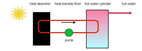
The main common component of solar collectors is the absorber plate. A coated metal plate absorbs the sun’s radiation and causes its temperature to rise above the ambient. The plate then releases energy through radiation and convection to its immediate surroundings. Heat is thus transferred to the heat-transfer fluid which in turn feeds the hot water system.


Types of collector: two general categories

  
Flat plate collectors

 
flat plate collector components
 
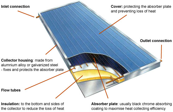
A flat-plate collector consists of an absorber, a transparent cover, a frame, and insulation. Usually an iron-poor solar safety glass is used as a transparent cover, as it transmits a great amount of the short-wave light spectrum.

Only very little of the heat emitted by the absorber escapes the cover (greenhouse effect).

In addition, the transparent cover prevents wind and breezes from carrying the collected heat away (convection). Together with the frame, the cover protects the absorber from adverse weather conditions. Typical frame materials include aluminium and galvanized steel; sometimes fibreglass-reinforced plastic is used.

The insulation on the back of the absorber and on the side-walls lessens the heat loss through conduction. Insulation is usually of polyurethane foam or mineral wool.
 

Evacuated-tube collectors

   
solar heat pipe components
   
In this type of vacuum collector, the absorber strip is located in an evacuated and pressure proof glass tube. The heat transfer fluid flows through the absorber directly in a U-tube or in counter-current in a tube-in-tube system. Several single tubes, serially interconnected, or tubes connected to each other via manifold, make up the solar collector. A heat pipe collector incorporates a special fluid which begins to vaporize even at low temperatures. The steam rises in the individual heat pipes and warms up the carrier fluid in the main pipe by means of a heat exchanger. The condensed liquid then flows back into the base of the heat pipe.

The pipes must be angled at a specific degree above horizontal so that the process of vaporizing and condensing functions. There are two types of collector connection to the solar circulation system. Either the heat exchanger extends directly into the manifold ("wet connection") or it is connected to the manifold by a heat-conducting material ("dry connection"). A "dry connection" allows to exchange individual tubes without emptying the entire system of its fluid. Evacuted tubes offer the advantage that they work efficiently with high absorber temperatures and with low radiation.
  

Flat plate v Evacuated tube

   
The debate over the relative performances of flat plate and evacuated tube collectors rumbles-on - without either side seemingly able to deliver the 'killer' argument.

In general though, it is probably safe to say that for a given absorber area, evacuated tubes are more likely to maintain their efficiency over a wide range of ambient termperatures and heating requirements. In constantly sunny climates flat plate collectors are more efficient whereas in more cloudy conditions their energy output drops off rapidly in comparison with evacuated tubes.


Heat distribution

 
Solar heating primary circuits transfer heat from the solar collectors to the pre-heat cylinder. They may be ‘Direct’ or, in the UK, the more usual ‘Indirect’.
   

'Direct' distribution

Pro Simplicity and increased efficiency over secondary circuits, through reduction of heat transfer loss
Con Subject to freezing unless the water is drained-back when the pump switches off, which puts constraints on the positioning of the collectors in relation to the feed tank
Con As new water continually flows through the collectors, they can be prone to ‘furring’ in the collector waterways resulting in loss of efficiency

'Indirect' distribution

Most circulation systems in the UK are indirect. Indirect circuits use a separate ‘heat-transfer fluid’ circuit to transfer heat from the collectors to the pre-heat cylinder. Their main advantage is that they can employ a wide range of materials and fluids as part of the circulation. There are different types of circulation that can be used:
 

Circulation Systems for 'Indirect' distribution
 

Passive circulation (aka ‘Gravity circulation’)

 Passive systems rely on gravity and the tendency for water to naturally circulate as it is heated, allowing water or heat-transfer fluid to move through the system without pumps. Because they contain no electric components, passive systems are generally more reliable, easier to maintain, and possibly longer-lasting than active systems.

Pro Electrical-powered pumps are not required to circulate the heat-transfer fluid
Con Careful planning is needed to optimise performance. Systems are prone to sluggish performance and there is a poor control of heating
Con Hot water storage tank needs locating above the collector level

  active and passive distribution systems
 

Active circulation (aka ‘Pumped circulation’)

 Pumped indirect circuits, incorporating a heat-transfer fluid including anti-freeze and corrosion inhibitor, are the most popular type of system in the UK.
The pump, controlled by a differential temperature controller, circulates the heat-transfer fluid from the collector panels through the heat exchanger in the hot water cylinder and back to the solar collectors for re-heating. The temperature sensors of the differential temperature controller are situated at the solar collector and on the hot water cylinder. They ensure that fluid is only circulated when the fluid in the collectors is hotter than in the cylinder.

Pro Integral protection against freezing
Pro Overheat control
Pro Heat is delivered from the collector at optimal rate
Pro Greater choice of collector and pipe layout
Pro Reduces heat loss through pipes
Con Increased complexity
Con Pump requires electricity (though this can be alleviated by PV supply)
Con More expensive


Storage tank configurations

 
The pre-heat configuration for the typical solar water heating system can be achieved in two ways, a separate pre-heat cylinder may be placed between existing cold water feed and the normal hot water storage, or the existing hot water storage cylinder can be replaced with a larger double heat exchange coil cylinder. Whichever design is chosen, extra storage volume is required. The space available to accommodate this extra storage capacity will often be the determining factor in the choice of system and also in the location of the storage cylinder.


Designing a solar hot water system


1 Sizing the storage cylinder

 Allow for 40 - 60 litres / person / day. Allow a minimum of 80 and preferably 100 litres storage per m2 of collector. A typical size for a family of four will be between 200 and 300 litres.
 

2 Selecting the type of storage cylinder

 Vented, mains pressure or thermal store. Mains pressure (un-vented) cylinders and thermal store cylinders are more expensive, but they enable the hot water to be maintained at the same pressure as the mains supply.
 

3 Selecting the collector type and system (see above)

  • Choose the type of collector- usually a flat plate or evacuated tube.
• Choose a direct or indirect distribution system (normally indirect in the UK)
• Choose gravity or pumped circulation
• Determine a pre-heating storage strategy – basically the choice is between a single cylinder with twin coils or the placement of a distinct pre-heat tank before the conventional cylinder.

 
4 Positioning the collector

  The collector position to give optimum all year round energy collection is roughly south facing and at a tilt of 35 degrees to the horizontal. The orientation and tilt angle will usually be determined by the roof angle. Collectors can face anywhere between south, south east and south west and have tilt angles commonly found on roof of UK houses ie 15 – 50 degrees without losing more than 5% of optimum annual energy collection. However, a steeper angle might be considered to optimise spring and autumn performance at the expense of summer surplus. Shading from trees, buildings etc. can produce significant losses in system efficiency and should be avoided.
 

5 Sizing the pipe line

 Piping is required to route and control the flow of heat transfer fluid between various components of the solar subsystem. The objective of the piping design is to accomplish all these functions with the best compromise between minimum parasitic power requirements and minimum capital costs. The pipe size should be determined according to the flow rate required for the solar heating system, maximum allowable flow velocity as well as economic aspect.

A lot of heat can be lost in a conventional solar water heating system because the pipes used can be wide. Issues to consider here include both surface area and pipe volume. Reducing surface area means reducing thermal losses. Using narrow microbore pipes in conjunction with low flow pumps instead of wider pipes will typically cut heat loss from pipes by over 50%.
 

6 Sizing the circulation pump

 Pumps should circulate heat transfer fluid at the design flow rate with minimum expenditure of electrical energy. Analysis of the complete pipe work will allow a total system head to be determined, describing variation of the total pressure drop of the system with operating flow rate. A suitable pump should provide the required flow rate at the necessary head while operating at or near its best efficiency.
 

What the design layout will show

• The overall system configuration and interfaces with the loads and auxiliary energy sources.

• The major system components and their relative locations (collectors, heat exchangers, pumps, hot water cylinders/storage tanks)

• The relative locations of the various pipe work components (valves, vents, expansion tank, relief valves, etc.)

• The relative location of the required sensors and instrumentation.
 

Some design considerations

• Before installing a solar collector system, ensure that energy efficiency measures have been effected. In particular, consult the publication 'Central Heating System Specifications' (CHeSS) (CE51/Year 2008) as a first step (see 'Downloads' below).

• Provision is likely needed to provide DHW where there is a shortfall, usually in winter, from solar hot water. There will be a number of options which will vary from electrical resistance heating through to gas or biofuel powered boilers. If opting for electrical heating, consideration should be paid to the carbon cost of grid provision.
• Ensure that there is at least 100mm of insulation around the hot water cylinder.

• All pipework is insulated - around 25mm is recommended

• Fit a non-return valve to avoid thermosyphoning.

• Ensure that all fabric penetrations are sealed to avoid air leakage.

• If collectors are installed at roof level, penetrations of the roof fabric should be carefullly detailed to avoid water ingress.

 
Relevant standards & independent performance information

 All collectors should be independently tested for their thermal performance to BS EN 12975 or BS EN 12976. To find out more about the performance characteristics of specific collectors, visit the CEN Keymark Scheme website for Solar Thermal products at www.estif.org/solarkeymark/


Costs

 Although the initial capital investment is high in comparison with conventional forms of domestic hot water heating, the fuel is, of course, free and the running costs are generally very low.

A pumped system will require electricity. This can be provided by a ‘green’ tariff or a small PV module mounted close to the collector, together with a light sensor.

Current installation costs for the average family home would amount to between £2,000 and £3,000 for a flat plate and between £3,000 and £5,000 for an evacuated tube installation.


Further information

 • Solar Trade Association ( www.solar-trade.org.uk )


Disclaimer
GreenSpec accepts no responsibility or liability for any damages or costs of any type arising out of or in any way connected with your use of this web site. Data and information is provided for information purposes only, and is not intended for trading purposes. Neither GreenSpec nor any of its partners shall be liable for any errors in the content, or for any actions taken in reliance thereon.